Previously[1] I described the initial stage of developing a library called rpi-peripherals[2] to access general purpose input output (GPIO) on a Raspberry Pi running Raspbian Linux in C++ from user land – that is there are no kernel mode parts to the library. The library was built on memory mapping the physical memory locations of the Raspberry Pi’s BCM2835 processor’s peripherals’ control registers using the dev/mem device accessed via a RAII (resource acquisition is initialisation[3]) resource managing class template called phymem_ptr.
Part 1 ended having described support for reading and writing single bit Boolean values representing the high/low voltage state of an associated GPIO pin in the forms of the ipin and opin types. Along the way we met various other entities such as the pin_id type representing the value of a BCM2835 GPIO pin, and the aforementioned phymem_ptr template.
This second instalment continues by describing adding support for some other IO functions and the challenges they presented.
But first…
One thing the ipin type does not support is waiting for a change of state to its associated GPIO pin before returning from a get operation. I really needed to address this as it was the very thing that started me on the road to writing my original Python Raspberry Pi GPIO library[4][5].
In the Python GPIO library the need for a blocking read was specified in the call to an open function and a suitable object would be returned that had a read operation that would wait until the specified edge event (rising, falling or either) occurred.
As mentioned the rpi-peripherals library directly accesses peripherals’ registers by memory mapping them curtesy of the phymem_ptr class template. The only readily available way to receive GPIO pin edge event notifications in user space is via the /sys/classes/gpio pseudo file system – as used by my Python library.
I did not like the idea of mixing GPIO access methods in ipin or some related class so I took a different approach. Instead a totally separate class called pin_edge_event encapsulates handling pin edge events via /sys/classes/gpio. In order to work with /sys/classes/gpio the GPIO pin’s number is required and the pin should be exported[4][6] and, of course, set up for input. As it happens an ipin instance, using the pin_export_allocator type to control access to GPIO pins between processes, just happens to fulfil all these criteria. Hence a pin_edge_event is constructed from an existing ipin instance together with an indication of which edge events are of interest:
  ipin in_pin{pin_id{23}};
  pin_edge_event pin_evt{in_pin,pin_edge_event::rising};
On construction the pin’s associated /sys/classes/gpio edge event file is opened. The pin is marked as having an associated pin_edge_event object as I thought it too confusing to allow more than one per ipin at a time. On destruction the pin is effectively closed for edge events by passing the file descriptor obtained during the open process to the Linux close function and the pin marked as not having an associated pin_edge_event object.
The implementation of pin_edge_event revolves around a call to pselect[7] – chosen over select for the fairly flimsy reason that it allows timeout resolution in nanoseconds rather than microseconds. The pin_edge_event interface allows waiting in various ways for an event to be signalled, from waiting indefinitely for an event to just checking to see if an event has been signalled:
  pin_evt.wait();
  assert(pin_evt.signalled());
In between, in the style of certain C++11 library APIs, there are wait_for and wait_until member function templates to wait for a specific amount of time or wait until a specific absolute time for an event to be signalled. They are templates as they use std::chrono::duration and std::chrono::time_point specialisations for their time parameters:
  auto wait_duration(std::chrono::milliseconds{100U});
  bool edge_event_signalled{pin_evt.wait_for(wait_duration)};
	  ...
  auto now(std::chrono::system_clock::now());
  auto wait_time(now+wait_duration);
  edge_event_signalled = pin_evt.wait_until(wait_time);
As can be seen from the example usage the signalled, wait_for and wait_until operations return a bool value which is true if an event was signalled. The wait operation does not return a value as it waits indefinitely for an event: if it returns then there was an event.
The final operation supported by pin_edge_event is the clear operation which needs to be performed after an edge event has been signalled. This has to do with how /sys/classes/gpio edge event handling works in that the value of the input pin the event occurred on needs to be read from the relevant file before another event can be waited on. Another /sys/classes/gpio edge event handling quirk is that a pin_edge_event object is initially in the signalled state:
  ipin in_pin{pin_id{23}};
  pin_edge_event pin_evt{in_pin,pin_edge_event::rising};
  assert(pin_evt.signalled());
  pin_evt.clear();
  assert(!pin_evt.signalled());
The time has come
Having sorted out single pin GPIO support the time had finally arrived to look at some of the other peripheral functions available. I thought that adding support for pulse width modulation (PWM) allowing me to make use of the motor controller on the Gertboard would be an interesting next step. But as ‘pulse width modulation’ hints at regular pulses are required which implies the use of a clock. In the case of the BCM2835 the PWM controller uses a separate but dedicated clock that has the same programming interface as the general purpose clocks that can be connected to GPIO pins. So in order to support PWM I would first have to provide support for clocks.
Like GPIO, clocks are controlled by a set of registers based at a specific physical address. Each clock is controlled by the clock manager peripheral and has its own set of two registers at an offset from this base address. Frustratingly the BCM2835 ARM Peripherals document[8] only gives the base address for the clock manager and the offsets from it for the three general purpose clocks’ register sets, not for clocks associated with other peripherals such as the PWM clock – although mention is made that the PWM clock is designated clk_pwm. I had to refer back to the provided Gertboard C code to locate the required offset value.
As with GPIO I started with the clock registers layout. Each clock controlled by the clock manager has the same register structure so I split the implementation into two structures: one describing a single clock, which I called a clock_record and the main clock_registers structure which contained a clock_record member for each supported clock carefully placed so that it was at the correct offset from the start of a structure instance – and yes there is a test to check they are at the expected offsets.
Like gpio_registers I provided member functions to get or set the individual fields within a clock’s registers. In the case of clock_registers which clock to operate on needs to be specified implying passing some sort of identifier. The easiest solution turned out to be to define the clock_id as a type alias for a pointer to clock_record member of clock_registers:
typedef clock_record clock_registers::* clock_id;Each member function of clock_registers takes a clock_id as a parameter and uses it to pass on the call to the identified clock_record member:
  clock_registers
  {
  ...
    clock_src get_source(clock_id clk) volatile const
    {
      return (this->*clk).get_source();
    }
    ...
  };
The specific clock ids were then defined as global constexpr clock_id instances initialised to the relevant clock_record member’s ‘address’ value, for example:
constexpr clock_id pwm_clk_id{&clock_registers::pwm_clk};Frequent division diversions
You would think the interface to a clock would be simple: specify the required frequency and provide operations to start, stop and possibly query the frequency and the running state. This is the sort of interface I wanted the public library clock support to provide.
However at the lower levels it turns out to be not so simple. First you have to supply the clock with a source of oscillation at a fixed frequency – the Raspberry Pi has a 19.2 MHz oscillator that can be used as an external (to the BCM2835) clock source which seems the easiest to use. Next it needs to be divided down to the required frequency.
Dividing down the clock source is more complex than just supplying an integer divider. Most required frequencies will have no integer divisor that produces an exact match. For example if the clock source oscillates at 1 MHz and we require a 134 KHz clock then the best we can do is divide by 8, yielding a frequency of 125 KHz, or by 7, yielding a frequency of around 143 KHz. So in addition to integer division the clocks provide something called MASH filtering (MASH it appears stands for Multi-stAge noise Shaping) – about which I know very little other than the information provided in the BCM2835 clock peripheral documentation. When using one of the three MASH filtering modes a fractional division value is used in addition to the integer division value. The result is that the actual clock frequency varies slightly between a minimum and maximum value, but the average frequency should be very close to that requested. The down side is that the MASH filtering modes introduce a bunch of constraints on maximum frequency and minimum integer divider value.
I wanted to work in terms of frequency rather than modes and divisor values. Providing a frequency type would allow the use of frequency units such hertz, kilohertz and megahertz. Thinking about this I noted that the inverse of frequency – or cycles per second – is a duration value – seconds per cycle. The standard library has the std::chrono::duration class template along with type aliases for specialisations representing various common time units such as microseconds and hours. I felt there should be some way to use std::chrono::duration to represent frequency. However, a solution was not immediate forthcoming so to keep moving forward and not get distracted further I effectively copied the required parts of the std::chrono::duration class template as my library’s frequency class template. The implementation was so similar that, in a somewhat hacked manner, when I produced a frequency_cast function template to cast between different frequency specialisation types, it was implemented in terms of std::chrono::duration_cast and std::chrono::duration – I had reached the end of my patience on these diversions! Completing the support for frequency I added a bunch of frequency specialisation type aliases for common frequency units: hertz, kilohertz and megahertz.
In addition to the frequency support I also added enumeration and simple class types and constant definitions to help with specifying a clock including a constant definition for the Raspberry Pi’s 19.2 MHz oscillator. These all live in the clockdefs.h library public header.
I created the clock_parameters class to aid bridging between frequencies and clock modes and divisors. Instances are created from a clock source and frequency (external clock source at 19,200,000 Hz for the Raspberry Pi’s 19.2 MHz external clock for example) along with the desired clock frequency specification combining the desired (average) frequency and an enumeration value specifying the level of MASH filtering required: maximum, medium, minimum or none – where none means use only an integer divisor.
During construction, after some basic parameter value checks, possibly repeated attempts are made to try to obtain a valid frequency value starting with the filter mode requested in the constructor parameters and falling back to lower levels if the maximum frequency produced is too high. If the frequency value exceeds even the substantially higher value allowed by the finally attempted integer only division mode a std::range_error is thrown. A std::range_error will also be thrown if the integer divisor is too small for the selected filter mode.
If no exception is thrown during construction then the various parameters can be queried via non-modifying accessor member functions.
Now there are two
The purpose of the clock_registers class is for a volatile instance to be mapped to the clock peripherals’ register block using a phymem_ptr<volatile clock_registers> instance. Some ability to detect trying to use the same clock peripheral multiple times would also be useful. So, as with the ipin and opin types and the gpio_ctrl singleton, a singleton type was created combining a phymem_ptr<volatile clock_registers>` instance with simple in-process clock-in-use allocation provided by the simple_allocator class template, specialised on the number of things available to allocate (in this case the 4 clocks: pwm_clk and gpclk 0, 1 and 2) and based around a std::bitset. Only in-process allocation management was provided because I could not see any straight forward way to provide an open inter-process allocation management scheme for clocks or other peripherals.
Setting up a GPIO pin for use as one of the three general purpose clocks not only requires access to the clock_ctrl instance but also to the gpio_ctrl instance so as to allocate the pin and set the correct alternate function for it. This would of course apply to any other peripherals supported by the library. When the only thing that needed to access the main GPIO registers were the ipin and opin types then gpio_ctrl could be left internal to the pin.cpp implementation file. But now there were two – the ipin/opin code in pin.cpp and the clock_pin code in clock_pin.cpp – some changes would be required.
As a bout of refactoring was inevitable it seemed prudent to decide on some conventions. First the library facilities were divided into the public API parts and library internal parts with the internal parts being placed in a nested internal namespace. Next, those headers required for using the public API were moved from the project src directory to the project include directory. This was always going to happen – it was just a matter of what and when. Finally, the gpio_ctrl code was moved out of pin.cpp and into its own library internal files gpio_ctrl.h and gpio_ctrl.cpp. A similarly named type and implementation file-pair were created for the clock peripherals: clock_ctrl in files clock_ctrl.h and clock_ctrl.cpp.
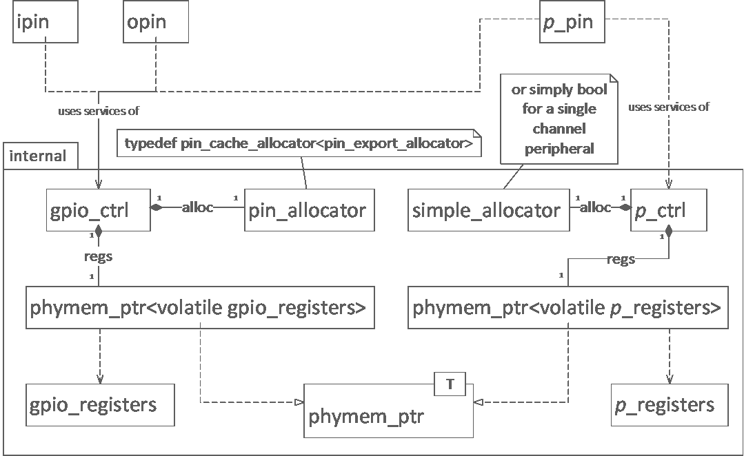
This lead to a basic pattern: for a peripheral p there would be a p_registers.h header file containing a p_registers class usually together with supporting entities that mapped p's register structure and associated values to C++ entities. This would be used, qualified volatile, to specialise a phymem_ptr mapped to the peripheral’s registers’ physical memory block start address along with some sort of in-use tracking in a p_ctrl singleton type implemented in p_ctrl.h and p_ctrl.cpp. The p_registers and p_ctrl types (and source files) are internal to the library. The public API would be presented by a type p_pin with p_pin.h being placed in the project include directory. Along the way there may be ancillary items which would often be internal to the library (such as phymem_ptr or the /sys/classes/gpio support in sysfs.h and sysfs.cpp) but sometimes – as with pin_id and those entities placed in the clockdefs.h header – would be part of the public API. Figure 1 shows the pattern as a UML class diagram; ipin and opin are included to show they only access gpio_ctrl while other peripherals additionally access their own p_ctrl type.
Can you do this?
The clock_pin class provides the library’s public support for general purpose clock functions on GPIO pins and unsurprisingly requires a pin_id specifying which GPIO pin to use. Wherein lies a problem. Unlike general input and output which all GPIO pins can perform, alternative functions – such as a general purpose clock (gpclk) function – can only be performed by a few, sometimes only one, pin. Which alternate functions a pin can perform is given in a table in the BCM2835 ARM Peripherals document.
On the other hand no pin supports more than one clock peripheral so if a pin supports one of the general purpose clocks then the pin number uniquely defines which general purpose clock (0, 1 or 2).
To help check if a pin supports a given peripheral function and which of the six alternate pin functions it is supported by I created the gpio_alt_fns module that provides a set of overloaded select query functions that select data from a statically initialised 2 dimensional array that defines the alternate functions each pin supports. The values are enumeration values taken from another table in the BCM2835 ARM Peripherals document that names the peripheral functions.
This allows questions such as which alternate function for pin p supports peripheral function f or which, if any, of a set of peripheral functions fs does pin p support? The select functions return a result_set object that has a partial STL container like interface allowing access via iterators, operator[]` and at and can be queried for size and being empty. The items in the result set are of a simple descriptor type specifying the pin, the special peripheral function and the alternative pin function it is supported on.
During the development of the gpio_alt_fns module I found that I had prefixed almost all identifiers with ‘pin_alt_fn_’. This seemed silly so I gave in and placed the whole lot in its own pin_alt_fn nested namespace.
Easy time?
So how easy is it to use a GPIO pin as a general purpose clock?
Like ipin and opin clock_pin uses RAII to manage the GPIO pin and general purpose clock resources. The most complicated operation is creating a clock_pin instance. Once successfully created the object can be used to easily start, stop and query whether the clock is running as well as obtain the values for the minimum, maximum and average frequencies the clock is using.
To create a clock the clock_pin constructor needs to be passed three things: the pin_id of the GPIO pin to use as a clock – which should support such a function of course, a clock source (passing rpi_oscillator defined in clockdefs.h is the easiest option), and finally a clock_frequency object specifying the desired clock frequency and the filter mode to apply. The clock_frequency type is defined in clockdefs.h.
For example we could create a 600 KHz clock with no MASH filtering (that is, using only integer division) like so:
  clock_pin clk{ gpio_gclk
               , rpi_oscillator
               , clock_frequency{kilohertz{600}, clock_filter::none}
               };
Note that gpio_gclk is defined in pin_id.h and yields a pin_id for GPIO pin 4, which supports gpclk0 as alternate function 0 and is available on pin 7 of the Raspberry Pi P1 connector. During construction all values are checked, with exceptions thrown in case of problems, and the GPIO pin and clock allocated and setup. The clock and pin are of course released during destruction, after ensuring the clock is stopped.
To check what frequencies are being used the frequency_avg, frequency_min and frequency_max member functions can be called. In this case we would expect a 600 KHz value for all three frequency values as only integer division of the clock source was applied and, as it happens, 600 KHz divides wholly into 19.2 MHz:
  assert(clk.frequency_min()==hertz{600000U});
  assert(clk.frequency_avg()==hertz{600000U});
  assert(clk.frequency_max()==hertz{600000U});
We can check if the clock is running – which just after construction it should not be:
assert(!clk.is_running());And of course we can start and stop the clock:
clk.start();
...
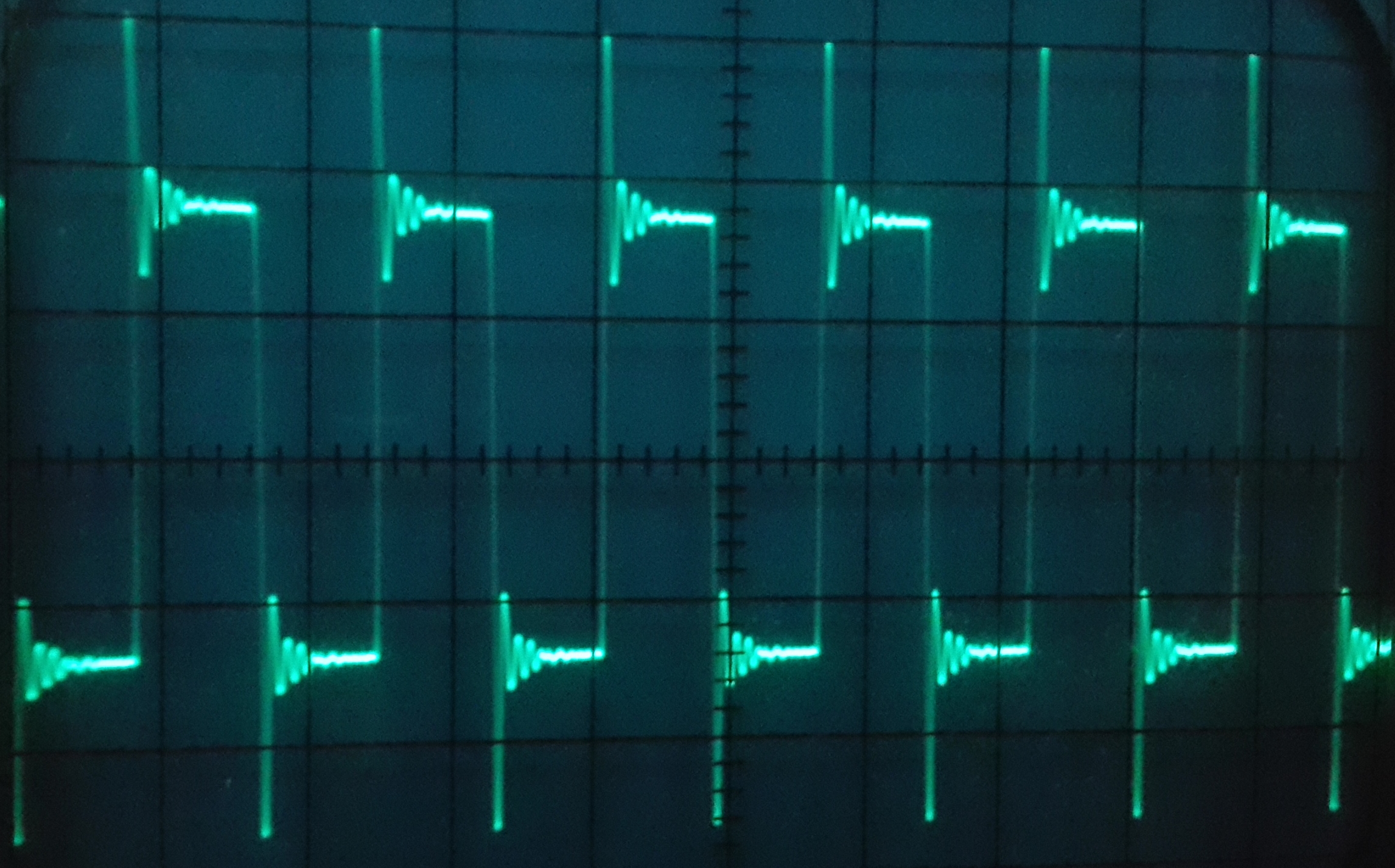
clk.stop();The output of gpclk0 running at 600 KHz can be observed by connecting GPIO pin 4 to the input of an oscilloscope as shown in Figure 2 – in which the time-base used is 1 µS per division.
After clocking up all those distractions…
Having provided support for clk_pwm and the general purpose clocks and refactored the library, I could return to pulse width modulation. PWM[9] allows control of power to devices such as motors by varying the ratio of high to low time per clock cycle (the duty cycle). You will notice in the clock trace shown in Figure 2 that these are equal, a ratio of 0.5: during each cycle the clock pulse is high for half the time and low for the other half of the time. PWM allows this ratio to be varied dynamically.
The BCM2835 has a single PWM controller that supports two channels that are referred to as PWM0 and PWM1 (as denoted by pin alternate functions) or channels 1 and 2 (as denoted by the PWM controller’s register descriptions), where channel 1 maps onto PWM0 and channel 2 to PWM1. Each channel can be used in either PWM mode or serialiser mode in which buffered data is written serially to the PWM channel’s GPIO pin. I included support for serialiser mode in the pwm_registers class implementation for completeness but do not provide support in the pwm_pin class. There are two PWM channels associated with the PWM controller but only one clock – clk_pwm – thus the clock settings used for clk_pwm apply to both PWM channels.
As it happens both PWM channels are used by the Raspberry Pi for stereo audio – using one PWM channel per audio channel. PWM0 can also be accessed for other purposes on GPIO pin 18 via pin 12 of the P1 connector. Of course using PWM for other things will most likely mess up the Raspberry Pi’s audio output.
The PWM peripheral has modes of usage I decided not to support: serialiser mode for a start. Other were DMA (direct memory access – an intriguing possibility – maybe one day) and FIFO buffering. I also decided to set certain other options to fixed values such as not to use inverted polarity and to only use the standard PWM sub-mode (the alternative so-called MS mode seemed like a half-way house between serialiser mode and standard PWM mode). Again, support was available in pwm_registers but not used by pwm_pin – other than to set the fixed feature values – generally to off (false).
Like the clock peripherals there are multiple (well, two) PWM channels so the member functions of pwm_registers mostly require a parameter to specify the channel (the exception being those functions relating shared resources such as DMA or the FIFO buffer). Unlike the clock peripherals there is no repeated register structure: some registers contain sections for each channel while others relate to one channel or the other. Hence a pwm_registers auxiliary enumerated type pwm_channel is used as a channel identifier and the enumerated values used to select either the required register or the required part of a register.
The two attributes that did need to be user-set for each channel were the range and the data. Together these are used to define the duty cycle ratio of the PWM output. The range value defines the number of bits over which the duty cycle high/low ratio waveform is spread and repeated. The data value defines how many of the bits of the range will be high and the algorithm used by the PWM controller will try to spread these out as evenly as possible. Taking the example from the BCM2835 ARM Peripherals document’s PWM section, if 4 bits of a range of 8 (a ratio of 4/8 or 0.5) are to be high then the pattern would be:
1 0 1 0 1 0 1 0
Rather than:
1 1 1 1 0 0 0 0
Or:
1 1 0 0 1 1 0 0
Each bit of the range would be used to set the high/low state of the associated GPIO pin changing from one bit’s state to the next on each clock ‘tick’, as provided by clk_pwm which should run at a reasonably high frequency – it is set to a default of 100 MHz by the hardware.
The handling of clk_pwm is split between pwm_pin and pwm_ctrl. The pwm_pin class provides static member functions to work with clk_pwm with the pwm_pin::set_clock member function performing a similar function to the constructor of clock_pin, but does not require a pin_id value as clk_pwm is never mapped to a GPIO pin. The other three functions provided are pwm_pin::clock_frequency_min , pwm_pin::clock_frequency_avg and pwm_pin::clock_frequency_max. They return the values for the frequencies used by pwm_clk in the same fashion as clock_pin::frequency_min , clock_pin::frequency_avg and clock_pin::frequency_max.
The low level details of setting up the clock that require access to clock_ctrl are delegated to pwm_ctrl::set_clock – an additional piece of functionality for the pwm_ctrl singleton type in addition to the phymem_ptr<volatile pwm_registers> and simple_allocator specialisation for the two PWM channels.
Setting pwm_clk up in the same fashion as the clock_pin usage example would look like so:
  pwm_pin::set_clock( rpi_oscillator
                    , clock_frequency{ kilohertz{600}
                    , clock_filter::none }
                    );
Which has the same parameters as the clock_pin object construction example less the initial pin_id parameter.
Where a pin_id is required – unsurprisingly – is in the construction of pwm_pin instances to specify which pin we want PWM output on. Details of which PWM channel (if any) and which alternate function of the GPIO pin is used for the PWM function being asked of a pin_alt_fn::select function. The other pwm_pin constructor parameter is an unsigned integer range value, defaulting to a value of 2400 – a fairly long range value which is divisible by quite a few values. Hence the only value needed to construct a pwm_pin object is a pin_id:
pwm_pin pwm{gpio_gen1};Where gpio_gen1 yields a pin_id value for GPIO pin 18 available on pin 12 of the Raspberry Pi P1 connector.
Now we have a pwm_pin object we can start and stop the PWM output, check whether it is running or not and set the ratio. The first three are simple to use and to implement:
  assert(!pwm.is_running());
  pwm.start();
  ...
  assert(pwm.is_running());
  ...
  pwm.stop();
  ...
  assert(!pwm.is_running());
The set_ratio operation, although easy to use is more interesting in its implementation. There are two forms, one that takes a double floating point value and another that takes a pwm_ratio value.
Before getting into pwm_ratio let’s first look at the overload taking a double. The value should be in the range [0.0, 1.0], with values outside this range throwing a std::out_of_range exception. The value is used to calculate the proportion of the range value to set for the PWM channel’s data register value with a value of 0.0 producing low values for the whole range, and a value of 1.0 all high values. For example the output could be set to be high for a quarter of the time like so:
pwm.set_ratio(0.25);I thought it would be nice to be able to express setting the ratio as a ratio. So pwm_pin.h includes a pwm_ratio class template, specialised by an integer type and a std::ratio specialisation (or similar type). Instances of specialisations of pwm_ratio hold a count value of the template integer parameter type, and define static constexpr values num (numerator) and den (denominator) equal to those values of the std::ratio specialisation template parameter type. For example for 0.3 count could be 3 with num and den set from a std::ratio with num 1 and den 10 as per std::deci, or maybe count is 30 with num and den from a std::ratio with num 1 and den 100 as per std::centi. I also defined a set of type aliases for pwm_ratio specialisations for ratios as numbers of tenths (pwm_tenths), hundredths (pwm_hundredths), thousandths (pwm_thousandths) and millionths (pwm_millionths).
The other form of the set_ratio operation is a member function template that takes a pwm_ratio specialisation, and hence requires the same template parameters as pwm_ratio. Using a ratio to set the PWM output to be high 25% of the time would look like this:
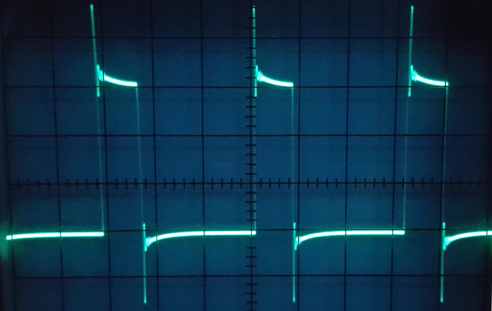
pwm.set_ratio(pwm_hundredths(25));Figure 3 shows the output of PWM0 using a 600 KHz clock, range of 2400 and a high ratio of 25% as observed by connecting GPIO pin 18 to the input of an oscilloscope this time using a time-base of is 2 µS per division.
References
-
Raspberry Pi Linux User Mode GPIO in C++ - Part 1, Ralph McArdell
-
See for example the Wikipedia Resource acquisition is initialization article
-
gpio.txt from Linux kernel, Raspberry Pi Foundation GitHub
(note: for the rpi-3.2.27 branch, use branch selection dropdown to select another) -
See for example the Wikipedia Pulse width modulation article