In early May 2014 I finally received from Adapteva[1] my Parallella Kickstarter project[2] mini-cluster reward of 4 Parallella boards plus network switch, power adapters, cables etc. The reward was originally supposed to be delivered in May 2013 but suffered many delays and setbacks, as documented on the Parallella website[3] and forums[4].
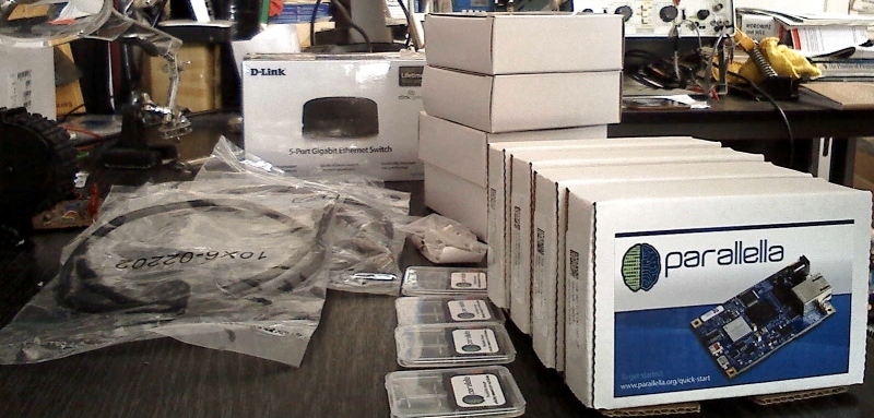
As I was going away for a couple of weeks shortly after it arrived I took some pictures of the unboxing (see Figure 1) and put it all to one side.
It was found that some components on the Parallella boards – the Zynq FPGA chip in particular – run hotter than passive cooling can handle. Adapteva included a self-adhesive heatsink with each board to attach to the Zynq FPGA chip, plus some fan assisted cooling is required.
So in late May I started thinking about powering and cooling four Parallella boards. Some sort of case wold be needed and I began drawing rough designs. Incorporating 5 power adapters and a mains power strip into a case would be cumbersome. Also, being UK based and with all the power adapters for USA mains sockets I decided not to bother using them at all (the 4 for the Parallella boards are still in their boxes). Instead I pressed into service a small PC PSU from a mini-PC case that was hanging around. It provides 5V at up to 12A and the 12V rail could be used for the fans. The 5 port D-Link router conveniently turned out to also require 5V, at up to 1A, supplied via a mini-USB connector.
I thought a couple of PC case fans would do for cooling. Having the Parallellas connected as a stack using the mounting posts provided (they are in the small bag behind the micro SD-cards in Figure 1) with one fan drawing air in below them and the other extracting the (warmed) air above them. Initially I considered 80mm fans but finally settled on 120mm units.
Having got tired of re-drawing designs by hand I downloaded and installed SketchUp from their website[5]. This allowed me to design a case around models of the actual components. My initial effort was a tower having the network switch in the base, the PSU at the top, and the Parallella-stack in the middle sandwiched between the two fans. I planned to use Perspex for the case component parts: 10mm square rods, 20mm right angle lengths, and 3mm thick sheet.
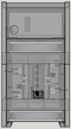
Then I saw the “My Name is Brian and I Build Supercomputers in My Spare Time” article on the Parallella web site[6] and revised my design such that the Parallellas were split into two pairs with each pair mounted next to each other on a board of Perspex sheet. The boards were mounted vertically left and right of centre. The network switch was placed in the centre gap, mounted on the back of one of the boards (handily it had mounting holes intended for wall mounting on its underside). This arrangement simplified the mounting of the Parallellas to the case. Figure 2 shows a front view of the model.
Early in June with the case design in a reasonable state I worked out how much of each type of Perspex was required, sourced and ordered more than enough – although I ended up with 25mm angle lengths – slightly wider than planned, plus a bunch of other bits and bobs: screws, nuts, locking washers, latching push buttons for the on/off switch (having spares is a good idea), cables and the like.
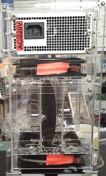
Having received all the material I spent the middle part of June building the case with much measuring, sawing, drilling, filing, screwing, re-doing and revising the design on the fly – I really should update the SketchUp model to reflect the final reality at some point. Figure 3 shows the back view of the result with PSU, fans and network switch.
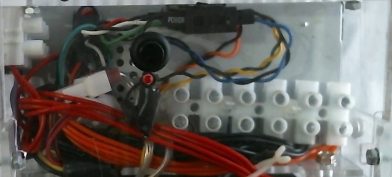
Late June saw me wiring up the power. The PC PSU of course had a mess of wires which needed to be tamed. All connectors were removed – even the 4 pin Molex connectors for which the fans had adapters as the resulting clump was too big to fit. The wires were then trimmed to their required length. The 3V3 and 12V lines could supply the highest currents with only one 12V wire used to power the fans. So the remaining wires were tinned and ‘parked’ in 15A/240V terminal strip – one slot for 3V3 and another at the other end for 12V. The remaining middle 4 slots were used to ‘park’ the mass of ground wires – with 4 wires out going for the Parallella boards. The remaining supply wires for -12V, 5V standby and one 5V wire were ‘parked’ in a smaller piece of terminal strip. Using terminal strip kept the cabling relatively neat and safe as well as making the power potentially available for use in the future.
The connections for network switch power, power on/off switch and power OK LED caused me a bit of a headache. I wanted to be able to disconnect each from the power supply easily if required but could not find suitable connectors. In the end I devised a system using a spare PC front panel set of connectors. These had a number of 2 pin connectors with cables attached and an odd double two row 16 pin connector that had pins on each side which were connected to each other in a 1-to-1 manner. This allowed two pin connectors wired to the relevant PSU lines to be plugged into one side and other two pin connectors going to switch, LED + resistor arrangement, and mini-USB connector for network switch power to be plugged into the other side. Figure 4 shows the results.
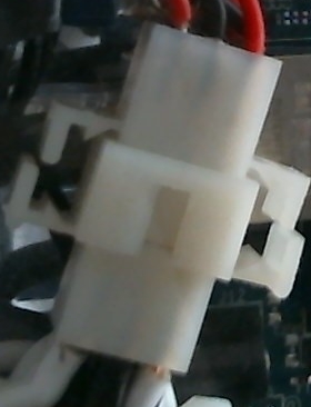
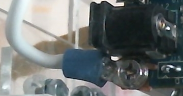
The Parallella power was provided by 4 pairs of wires: one 5V wire and one ground wire for each board. I had, from around 25 or so years ago, some male and female power pins and a pair of 9-hole housings to suit and these were used to provide the PSU to Parallellas power connection (figure 5). The connector to Parallella side used fork terminals to provide connections to the Parallellas via their mounting holes. One problem I discovered with using fork terminals: if care is not taken then the tine nearest to the barrel connector can touch the exposed 0V tag of the barrel connector shorting the supply (figure 6).
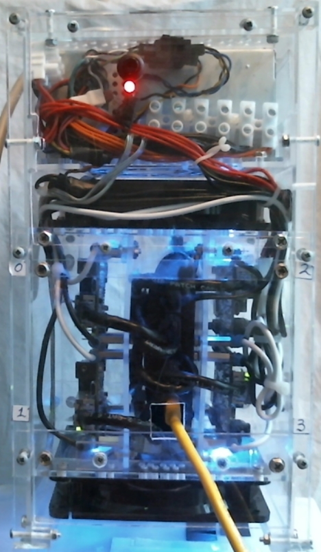
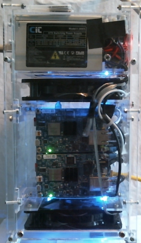
Figures 7 and 8 show the completed mini-cluster powered up.